


Reference: DWM14042301
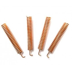
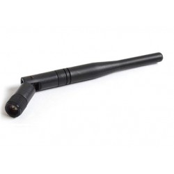
Spring-Antenna 315MHz /433MHz /868MHz /915MHz
Spring antenna is specialized for wireless data transmission. This antenna with good performance of V.S.W.R, small size design, easily installation, stable performance and good anti-shock and anti-aged compatible for Hoperf Modules.
Price
$1.05
Regular price
$1.35
In stock