AT Command for UHF/VHF Walkie Talkie radio module

Description

The default working mode of the module is wideband, the transmit/receive frequency points are 150.050MHz, and the transmit/receive subcarriers are 67Hz. If no AT command is received to change the parameters, the module will work according to the default parameters. 
In data communication mode, the PTT pin must remain high. 
The normal operation of the module requires a 3.6-4.2V power supply and at least 1A of current. When the PD pin is at a high level, the module works. When the PD pin is at a low level, the module is turned off.

1. After the module is powered on, if no AT command is received, the default working parameters are: Bandwidth: Wideband 
Transmit frequency: 150.050MHz  
Receive frequency: 150.050MHz
Transmit subcarrier: 67Hz 
Receive subcarrier: 67Hz
Squelch level: 2
Scrambler: Off 
Compression: Off
Transmit timeout: Off
MIC sensitivity: 6
Audio output level: 62. In data communication mode, the PTT pin cannot be low level. 3. Working conditions of the module:Recommended DC voltage: 3.6-4.2V, the power supply must provide more than 1A current; 
The PD pin of the module must be high level; 
PD can be used as the on/off control pin of the module. 

AT command type

1) Command without parameter:

AT+<command>,eg.:AT+DMOCONNECT

2) Command with parameter:AT+<command>=<par1>,<par2>,<par3>…

3) Response command format are as below :

<CR><LF><command string>

<CR><LF>

<CR> Enter,0x0D

<LF> Newline,0x0A。

1.2 AT Command format

All the AT command started with “AT”, And ended with<CR>。

The UART port default setting are as below:

8 bit data,

1 bit stop,

without parity ,

CTS/RTS,

9600 baut

ATcommand response format:

<CR><LF><command string><CR><LF>

Simplified instruction for SR105, SR110 and SR120 Serial for the older version SR-FRS-V and SR-FRS-U AT command you can visit this link: https://docplayer.net/91122125-Sr-frs-0w5-wireless-transmit_receive-data-transfer-module-uhf-vhf-uart-communication-protocol.html

AT+DMOGRP(old version command AT+DMOSETGROUP ): Set transmit frequency, receive frequency, sub audio, bandwidth, busy channel lockout, transmit power. 

Description: Set frequency, sub audio frequency, power, bandwidth and other parameters.

Format: AT+DMOGRP=RFV,TFV,RXCT,TXCT,Flag,Flag1Example (text input):
AT+DMOGRP=450.02500,450.02500,RR,TT,0,0  (Carriage return/line feed)
Because RR and TT represent sub audio frequencies, they cannot be entered directly in text format; see explanation below. RFV, TFV, frequency values, must be 5 digits after the decimal point.

Example (HEX input):
41 54 2B 44 4D 4F 47 52 50 3D 34 35 30 2E 30 32 35 30 30 2C 34 35 30 2E 30 32 35 30 30 2C 70 06 2C 70 06 2C 30 2C 30 0D 0A Response:
+DMOGRP:0 Success
+DMOGRP:1 Failure

Parameter description:

RFV: Receive frequency value:400.00000-480.00000MHZ (integer multiple of 6.25K or 2K5)
TFV: Transmit frequency value:400.00000-480.00000MHZ (integer multiple of 6.25K or 2K5)
Note: The transmit frequency and receive frequency can be the same frequency or different frequencies (ASCII)
RXCT: DO D1 Receive coding has 2 BYTES. (Hexadecimal number)
Format: BCD code (see explanation below)
The low four bits of RXCT1 are the decimal part. If DEC is not set, fill in FF FF. For example:
67.7 D0D1 data 0x77 0x06 
D023N D0D1=23
80 D244N D0D1=44
82 D023I D0D1=23 
C0 D251I D0D1=51 C2
TXCT: Transmit encoding (hexadecimal number), the same as receive encoding.
Flag: (ASCII)
Bit0 Busy channel lockout (0: Off 1: On) (default off)
Bit1 Wide/narrow band (0: Wideband 1: Narrowband) (default wideband)
FLAG = bit1 *2+ bit0;
Flag1: (ASCII) (Invalid for SR105U model, please set FALG1 to 0)
Bit0 High/low power (0: High power 1: Low power) (default high power)
Default: Transmit/receive frequency 450.05000, sub audio 67Hz.
FLAG1 = 0; 

1. RXCT and TXCT are HEX, not ASCII, so commands cannot be sent directly in text format. For example:Enter the command in text mode on the computer:
AT+DMOGRP=450.02500,450.02500,RR,TT,0,0(press Enter)In the PC serial port tool, switch to send in hexadecimal (HEX) format. The result is:
41 54 2B 44 4D 4F 47 52 50 3D 34 35 30 2E 30 32 35 30 30 2C 34 35 30 2E 30 32 35 30 30 2C 52 52 2C 54 54 2C 30 2C 30 0D 0A
Red represents RR, TT corresponding positions
R R  T TIf the sub audio frequency you need is 67.0, after format conversion, the corresponding sub audio is 70 06; Replace RR and TT with 70 06, so the correct command is:
41 54 2B 44 4D 4F 47 52 50 3D 34 35 30 2E 30 32 35 30 30 2C 34 35 30 2E 30 32 35 30 30 2C 70 06 2C 70 06 2C 30 2C 30 0D 0A
Then click Send.Note:
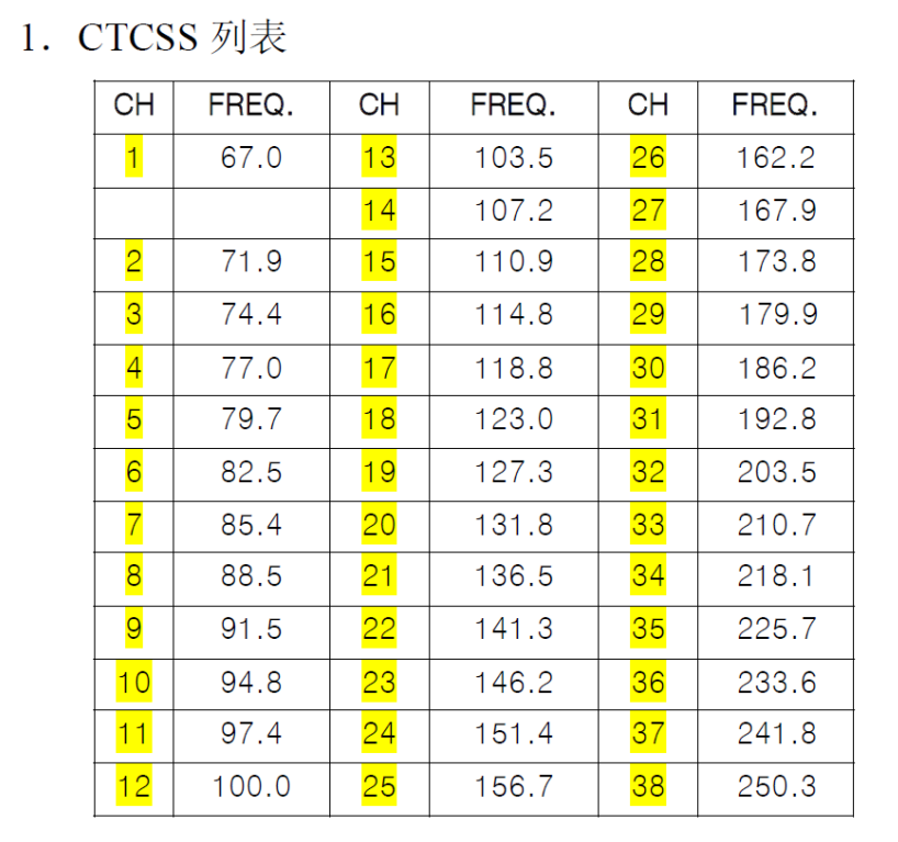
1. Sub audio setting method:
1) For analog sub audio 
For example: 67.0 67.0 →06 70→ D0 D1= 70 06 
250.3 250.3 →25 03→ D0 D1= 03 25
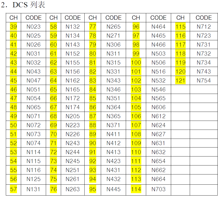
2) For digital sub audio 
Positive polarity D1 MSB is 8; for example: 
D023N 023→8023→ D0 D1=23 80 
D244N 244→8244→ D0 D1=44 82
Negative polarity D1 MSB is C;
D023I 023→C023→ D0 D1=23 C0
D251I 251→C251→ D0 D1=51 C22. FLAG/FLAG1 setting method
BIT1 BIT0 according to the 8421 BCD code to take the value
FLAG = BIT1 * 2 + BIT0
FLAG1 = BIT1 * 2 + BIT0
For example:
1) FLAG: Bit1 = 1; bit0 = 0
FLAG corresponds to BCD code 2 + 0 = 2; FLAG set value is 2;
2) FLAG: Bit1 = 1; bit0 = 1
FLAG corresponds to BCD code 2 + 1 = 3; FLAG set value is 3; 
2) FLAG: Bit1 = 0; bit0 = 1
FLAG corresponds to BCD code 0 + 1 = 1; FLAG set value is 1; 

AT+DMOSAV(old version command AT+DMOAUTOPOWCONTR ): Automatic power saving function setting

CommandDescription: Set the automatic power saving function of the module. 

Format: AT+DMOSAV=X

Example:
AT+DMOSAV=0(Carriage return/line feed)

Response:
+DMOSAV:0 Success
+DMOSAV:1 Failure 

Parameter description:
X:
0 Set power saving on 
1 Set power saving off 
(The default is 0, automatic power saving is turned on) 

AT+DMOVOL( old version command AT+DMOSETVOLUME ): Output volume setting 

Description: Set the audio output volume level of the module. The larger the value, the greater the volume. Format: AT+DMOVOL=X 

Example: 
AT+DMOVOL=1 (Carriage return/line feed) 

Response: 
+DMOVOL:0 Success 
+DMOVOL:1 Failure  

Parameter description:
X: Volume level parameter value range: 1-9 
(The default is 6) 

AT+DMOVOX( old version command AT+DMOSETVOX ): Voice control function setting  

Description: Set the voice control trigger sensitivity of the module. The larger the value, the more sensitive the trigger.

Format: AT+DMOVOX=X

Example:  AT+DMOVOX=0 (Carriage return/line feed)

Response:
+DMOVOX: 0 Success 
+DMOVOX: 1 Failure 

Parameter description: 
X: Voice control level parameter value is 0-8 levels,  (default off) 
0: Turn off voice control trigger transmission 
1-8: Turn on voice control and represents the sensitivity level of voice control trigger.  (The default is 8) 

AT+DMOFUN( old version command AT+DMOSETMIC ): Parameter settings: squelch level, MIC sensitivity, transmit timeout, compression, scrambling 

Description: Set the parameters of the module: squelch level, transmit timeout, MIC sensitivity, scrambling, compressionFormat: AT+DMOFUN=SQL,MICLVL, TOT,SCRAMLVL ,COMP Example: 
AT+DMOFUN=2,6,0,0,0(Carriage return/line feed) Response: 
+DMOFUN:0 Success 
+DMOFUN:1 Failure  

Parameter description: 
SQ: Squelch level: 0-8 (0: Monitor mode)
MICLVL: MIC sensitivity level parameter value is 0-8 levels (default level 5) 
TOT: Transmit timeout, setting range: 0~9; (default off)
0: Turn off transmit timeout 
1~9: Represent transmit timeout 1 minute to 9 minutes respectively)
SCRAMLVL: Scrambling function parameter value 0-7.  (0 means scrambling is off), (default off)
COMP: Compression function switch 
0: Off 
1: On (default off)

AT+DMOMES(old version command AT+DMOMES ) SMS sender sending command 

Description: Set the SMS sending function of the module, air rate 1200 baud rate 

Format: AT+DMOMES=Lxxxxxxx Example: 
AT+DMOMES=7ABCDEFG(Carriage return/line feed)    
41 54 2B 44 4D 4F 4D 45 53 3D 07 41 42 43 44 45 46 47 0D 0A

Response: 
+ DMOMES:0 Success 
+ DMOMES:1 Failure  

Parameter description:
L: The character length of the SMS (hexadecimal number, maximum length 70BYTE).
XXXXXXX: SMS content

Notes:
1. When sending SMS in text format, the “7” in the text actually represents 0X37 and will be wrong. Before sending, you must switch to HEX format to send, and manually change 0X37 to 0X7.
Text input, directly converted to HEX, the length here is wrong:
41 54 2B 44 4D 4F 4D 45 53 3D 37 41 42 43 44 45 46 47 0D 0A 
You need to change 37 to 07, correct as follows:
41 54 2B 44 4D 4F 4D 45 53 3D 07 41 42 43 44 45 46 47 0D 0A2.

Note: The new modules cannot be compatible with the old products of the same type.

AT+DMODTF DTMF: sending and receiving (please contact customization, the standard shipping version does not contain this function)  

 Send DTMF signal

Description: Send DTMF digits 0-9 or letters ABCD*#

Format: AT+DMODTF=XY Example: AT+DMODTF=09 

Response: 
+DMODTF:0 Success
+ DMODTF:1 Failure Parameter description: 
XY send digits 
00 send DTMF code: 0 
01 send DTMF code: 1 
02 send DTMF code: 2 
03 send DTMF code: 3 
04 send DTMF code: 4
05 send DTMF code: 5 
06 send DTMF code: 6 
07 send DTMF code: 7 
08 send DTMF code: 8
09 send DTMF code: 9
XY send characters:  
10 send DTMF: A
11 send DTMF: B
12 send DTMF: C 
13 send DTMF: D
14 send DTMF: *
15 send DTMF: # 

Receive DTMF signal  

Description: After the module demodulates the received DTMF, it automatically uploads it through the serial port. 

Format: +DMODTF:XY Example: +DMODTF:09 

Response:  None

Parameter description: 
XY received digits  
00 received DTMF code: 0 
10 received DTMF code: 1 
11 received DTMF code: 2
12 received DTMF code: 3
13 send DTMF code: 4
14 received DTMF code: 5
15 received DTMF code: 6 
16 received DTMF code: 7
17 received DTMF code: 8 
18 received DTMF code: 9
XY received characters: 
10 received DTMF: A
11 received DTMF: B 
12 received DTMF: C
13 received DTMF: D
14 received DTMF: *
15 received DTMF: # 

AT+DMOCONT: Handshake instruction, communication connection test

Description: Communication handshake command 

Format: AT+DMOCONT Example: AT+DMOCONT (Carriage return/line feed) 

Response:  +DMOCONT:0 

Parameter description: None. 

AT+DMOREST: Restore factory settings

Description: Reset all parameters to factory default settings 

Format: AT+DMOREST 

 Example: AT+DMOREST (Carriage return/line feed) 

Response: +DMOREST:0  

Parameter description: None. 

AT+DMOEND: Tail tone setting 

AT+DMOEND Echo tail setting (please contact customization if needed, standard shipping version does not contain this function) 

Description: Turn on or off echo tail setting 

Format: AT+DMOEND=X 

Example: AT+DMOEND=0 (Carriage return/line feed)

Response: +DMOEND:0  

Parameter description: 
X is an on/off switch to open or close the echo tail function 
0: Turn on echo tail; (default) 
1: Turn off echo tail;  

Special instructions: Unless there is a clear requirement, please be sure not to turn off the echo tail. Turning off the echo tail will cause a large noise when the receiving end closes the speaker at the end of transmission. 

AT+DMORSSI: RSSI signal strength query

Description: Query received signal strength, 

Format: AT+DMORSSI  

Example: AT+DMORSSI (Carriage return/line feed) 

Response: + DMORSSI:XXX XXX is the signal strength value, just a relative value;

Parameter description: 
XXX: 000-127 

Data reference: (The larger the returned value, the stronger the signal)

Receiving sensitivity: RSSI
OFF <30
-120 036
-110 046
-100 055
-90 065
-80 075
-70 085
-60 094
-50 103
-40 115
-30 127
-20 127
-10 127
0 127

1. Parameter settings can be retained after power off; 
2. After the module is powered on, you must delay 0.5S before setting various parameters of the module; 
3. Parameters cannot be set when the module is in the transmit state; 

AT+DMOVERQ: Query software version number 

Description: Query module version command 

Format: AT+DMOVERQ 

Example: AT+DMOVERQ  (Carriage return/line feed) 

Response:+DMOVERQ:105U-VXXX  

Parameter description: 
XXX is the software version number, such as 100 

LT-W208 LoraWAN Soil NPK Sensor node Connect to Dragino gateway and ChirpStack

Overview

LT-W208  LoraWAN Soil NPK Sensor node is powered by battery, with long battery life, no wiring, and convenient construction.Useing the LoraWAN spread spectrum technology which Products are widely used in the field of smart farming. this document shows a basic idea about LT-W208  LoraWAN Soil NPK Sensor node Connect to Dragino gateway and ChirpStack.

1.Connect via LAN port with direct connection from PC ,Power on the gateway, access the gateway with the url( 10.130.1.1) in the browser( Access via WiFi AP network http:// IP_ADDRESS:8000 ), click LORA, and select correct frequency plan and frequency band mask. The default frequency band mask is: 1 . click Save & Apply .

2. Select the LORANWAN configuration interface to set the NS address of the gateway. We use The CHIRPSTACK server as example for the test, so select CUSTOM and select it according to the real server address.  Record the GATEWAY EUI information. click Save & Apply.

3. Log in to the ChirpStack server Enter the IP address and port, enter the user name and password, and click Login .

4. Add a LORAWAN gateway. Click Gateways and CREATE to enter the gateway EUI, which is the gateway EUI shown in the pictures below. 

5. Add an app Click Applications and click CREATE to add an app. 

6. Click Add Application, add device, click CREATE to add device name.

7. Device Description DEVEUI of device, select the corresponding frequency band, and click Add Device, as shown in picture below.  AU915 communication is not very stable, which may be related to the frequency band. It is recommended to disable the frame count verification function. 

8. Add APPKEY, enter APPKEY parameter in Application Key, and click SET device-keys.

9. Click DEVICE DATA to view the DATA.

10. DECODE Example

function Decode(fPort, bytes, variables) {

  var paramLength = bytes[2]/2;

  var params = new Object();

  for(var i=0;i<paramLength;i++)

  {

    params[“param”+i] = bytes[3+i*2]*256+bytes[4+i*2];

  }

  return params;

}

DECODER

function decodeUplink(input) {
var params = new Object();
params[“N”] = input.bytes[23]256+input.bytes[24]

params[“P”] = input.bytes[25]256+input.bytes[26]
params[“K”] = input.bytes[27]256+input.bytes[28]

params[“BAT”] = (input.bytes[29]256+input.bytes[30])/1000
return {
data: params
};
}

TTN Device Hardware options

Brand: stmicroelectronics Model: nucleo-wl55jc1 Hardware version: 1.0 Firmware version: 1.0

TTN Decoder

function decodeUplink(input) {
var params = new Object();
params[“N”] = input.bytes[23]256+input.bytes[24]
params[“P”] = input.bytes[25]256+input.bytes[26]
params[“K”] = input.bytes[27]256+input.bytes[28]
params[“BAT”] = (input.bytes[29]256+input.bytes[30])/1000
return {
data: params
};
}

SX1276-LoRa one article is enough

This article will list all of the resources for Lora’s development and application. We will keep updating when we find any valuable resources. Here are the categories: Products, Datasheet, Libraries, Applications, accessories.

Products

Datasheet

SX1276-7-8-9 Datasheet

Development Support Documents

Introducing LoRa™ !

Libraries

A LoRaWan Gateway in LUA

Arduino library for LoRa modules based on SX127x/RFM9x chips

Arduino Core for STM32L0

Arduino LoRa E32 Series device library complete and tested with Arduino, esp8266 and esp32.

LoRa node on nRF52

A complete model of a low-cost sensor node device using solar energy and an sx1276 transmitter for a LoRa Wireless Sensor Network.

The Things Network Gateway based on Raspberry Pi and resin.io

A platform-agnostic driver for Semtech SX1276/77/78/79 based boards. It supports any device that implements the embedded-hal traits. Devices are connected over SPI and require an extra GPIO pin for RESET.

wMbus receiver based on STM32L476 Nucleo and Hope RF95.

AzureIoT Hub Windows 10 IotCore Field Gateway for LoRa capable device.

Port for PSoC devices of the IBM LMiC for SEMTECH LoRa radios .

Библиотека управления приемопередатчиком sx1276/7/8/9

C# Semtech SX127X/RFM9X LoRa library for Windows 10 IoT Core powered devices 

Arduino library for LoRa modules based on SX127x/RFM9x chips modified for Linux and possible Orange/Raspberry PI

A library for sending data using SX1276 LoRa radio using PIC as MCU.

P8X32A/Propeller driver object for the Semtech SX1276 LoRa transceiver chip

ATTiny1614 + SX1276 + BME280

LoRa RFM95/SX1276 libraries for PIC 8 bit microcontrollers

Project-Applications

  1. SLoRa – Wireless weather station for agriculture Project by DorijanLow power, Long-range wireless weather sensor system to detect potential frosting and alert the farmer to take action.
  2. ESP32 – LoRa – OLED Module Project by data Get the most out of your (heltec/ttgo/aliexpress) ESP32 LoRa OLED development board.
  3. Spy Thing Project by Ville TiukuvaaraA tracking device with GPS, a digital microphone, LoRa transceiver, and an STM32 microcontroller.
  4. Using Ultrasonic sensor with Lora Ra-02 ( or SX1276) use a wireless ultrasonic sensor to monitor the water level in the well/tanks at our cottage. 

DWM-HEXADUO AIR PURIFIER USER GUIDE

DWM-HexaDuo Air Purifier is easy to use, and helps to produce a clean and safe enviroment. It’s an energy-efficient high performance air purifier The Size is compact enough to place in anywhere.

1.Packing list

dwm-hexaduo-air-purifier-washable-electrostatic-filter-kills-airborne-bacteria-package-list

dwm-hexaduo-air-purifier-washable-electrostatic-filter-kills-airborne-bacteria-package-list

2.Components

dwm-hexaduo-air-purifier-washable-electrostatic-filter-kills-airborne-bacteria-components

dwm-hexaduo-air-purifier-washable-electrostatic-filter-kills-airborne-bacteria-components

3.Operations

DWM-HEXAONE-AIR-PURIFIER-USER-GUIDE-operation

DWM-HEXAONE-AIR-PURIFIER-USER-GUIDE-operation

3.1 Operation Modes

3.1.1 Clean Mode

When the accumulated operation time reach two weeks,The cleaning

indicatorcleaning-indicatorwill be lights up to remind the user to clean the collection array.

Press thefan-speed-press fan speed level button for 3sec to acknowledge the cleaning alert. The cleaning inducator buttton will be turn off.Power off the unit and take out collection array to clean.Clean and dry the collection array before re-install back to the device.

3.1.2 Protection Mode

When the device is operating, and the collection array is removed suddenly, then the device will be stop working, and all indicators will flash at the same time as an alert to user.when the device is powered on without the collection array the device will not work, and all Indicators will flash at the same time as an alert to user. the user needs to shut down the device, and put the collection array into the device, and then the unit will return to nomal operation mode.

3.1.3 Failure Mode

When the collection array accumulates dust anvil or debris and over the collection limit, the device will be stop operation, and all of te lights will flash at the same time as alert to user.The user will need to shut down the device and clean the collection array.

4.Instructions

4.1 connect the power adptor

dwm-hexaduo-air-purifier-washable-electrostatic-filter-kills-airborne-bacteria-connect-power

dwm-hexaduo-air-purifier-washable-electrostatic-filter-kills-airborne-bacteria-connect-power

Note:

In order to have better effect of air purification, the circular clearance area should be 1.6ft(0.5m) in radius when the device is placed at the center.

dwm-hexaduo-air-purifier-washable-electrostatic-filter-kills-airborne-bacteria-room

dwm-hexaduo-air-purifier-washable-electrostatic-filter-kills-airborne-bacteria-room

4.2 Turn On the device

DWM-HEXAONE-AIR-PURIFIER-USER-GUIDE-power-on

DWM-HEXAONE-AIR-PURIFIER-USER-GUIDE-power-on

Note:

You may hear static noise when the unit is first time started, This is nomal due to setting up of the electrostatic field for capturing the air borne particles.

4.3 Adjust the required speed

DWM-HEXAONE-AIR-PURIFIER-USER-GUIDE change-fan-speed

DWM-HEXAONE-AIR-PURIFIER-USER-GUIDE change-fan-speed

Note:

“Turbo Fan Mode” is a 20-min turbo cleaning setting that rapidly purify the air with its maximum power in shortest possiable time, the fan speed will then resume to low level for power saving and silent operations.

4.4 Stretch the bipod of the unit and put the unit on a flat table or floor.

dwm-hexaduo-air-purifier-washable-electrostatic-filter-kills-airborne-bacteria-set

dwm-hexaduo-air-purifier-washable-electrostatic-filter-kills-airborne-bacteria-set

4.Clean and Maintenance

4.1 Power off the unit and turn the collection array upright to unlock and then remove it from the unit.

dwm-hexaduo-air-purifier-washable-electrostatic-filter-kills-airborne-bacteria-open-clean

dwm-hexaduo-air-purifier-washable-electrostatic-filter-kills-airborne-bacteria-open-clean

4.2 For strong or sticky oil type pollutant,spray soft cleaner and use cleaning tool to clean the individual dust plate.

dwm-hexaduo-air-purifier-washable-electrostatic-filter-kills-airborne-bacteria-maintenance-clean

dwm-hexaduo-air-purifier-washable-electrostatic-filter-kills-airborne-bacteria-maintenance-clean

4.3 Immerse the whole collection array into water or rines the collection array throroughly under running water.

dwm-hexaduo-air-purifier-washable-electrostatic-filter-kills-airborne-bacteria-open-clean-1

dwm-hexaduo-air-purifier-washable-electrostatic-filter-kills-airborne-bacteria-open-clean-1

4.4 Dry the collection array before re-install it back to the unite,install the collection array in vertical direction and then turn to desire air flow angle and lock it.

dwm-hexaduo-air-purifier-washable-electrostatic-filter-kills-airborne-bacteria-maintenance-clean-1

dwm-hexaduo-air-purifier-washable-electrostatic-filter-kills-airborne-bacteria-maintenance-clean-1

dwm-hexaduo-air-purifier-washable-electrostatic-filter-kills-airborne-bacteria-note

dwm-hexaduo-air-purifier-washable-electrostatic-filter-kills-airborne-bacteria-note

5 Trouble shooting

Not Operating ,No light indication

-Ensure the collection array is connected with the fan body firmly.

-Ensure the AC adaptor is fully inserted into the AC outlet and its plug is connected to the DC jack of the air purifier.

-Press the Power button momentarily to observe that it’s light up.

Not operating,indicator flashing

-Check the collection array, for too heavy dirt or any clogging by hairs or fibers.

-Clean the collection array as needed and install back ion the air purifier.

If you want buy one pls visit our online shop DWM-HexaDuo Air Purifier .

DWM-HEXAONE AIR PURIFIER USER GUIDE

DWM-HEXAONE AIR PURIFIER is easy to use, and helps to produce a clean and safe enviroment. It’s an energy-efficient high performance air purifier The Size is compact enough to place in anywhere.

1.Packing list

DWM-HEXAONE-AIR-PURIFIER-USER-GUIDE-package

DWM-HEXAONE-AIR-PURIFIER-USER-GUIDE-package

2.Components

WM-HEXAONE-AIR-PURIFIER-USER-GUIDE-Componets

3.Operations

DWM-HEXAONE-AIR-PURIFIER-USER-GUIDE-operation

DWM-HEXAONE-AIR-PURIFIER-USER-GUIDE-operation

3.1 Operation Modes

3.1.1 Clean Mode

When the accumulated operation time reach two weeks,The cleaning

indicatorcleaning-indicatorwill be lights up to remind the user to clean the collection array.

Press thefan-speed-press fan speed level button for 3sec to acknowledge the cleaning alert. The cleaning inducator buttton will be turn off.Power off the unit and take out collection array to clean.Clean and dry the collection array before re-install back to the device.

3.1.2 Protection Mode

When the device is operating, and the collection array is removed suddenly, then the device will be stop working, and all indicators will flash at the same time as an alert to user.when the device is powered on without the collection array the device will not work, and all Indicators will flash at the same time as an alert to user. the user needs to shut down the device, and put the collection array into the device, and then the unit will return to nomal operation mode.

3.1.3 Failure Mode

When the collection array accumulates dust anvil or debris and over the collection limit, the device will be stop operation, and all of te lights will flash at the same time as alert to user.The user will need to shut down the device and clean the collection array.

4.Instructions

4.1 connect the power adptor


DWM-HEXAONE-AIR-PURIFIER-USER-GUIDE-connect-adapter

DWM-HEXAONE-AIR-PURIFIER-USER-GUIDE-connect-adapter

Note:

In order to have better effect of air purification, the circular clearance area should be 1.6ft(0.5m) in radius when the device is placed at the center.

DWM-HEXAONE-circular-clearance-area

DWM-HEXAONE-circular-clearance-area

4.2 Turn On the device

DWM-HEXAONE-AIR-PURIFIER-USER-GUIDE-power-on

DWM-HEXAONE-AIR-PURIFIER-USER-GUIDE-power-on

Note:

You may hear static noise when the unit is first time started, This is nomal due to setting up of the electrostatic field for capturing the air borne particles.

4.3 Adjust the required speed

DWM-HEXAONE-AIR-PURIFIER-USER-GUIDE change-fan-speed

DWM-HEXAONE-AIR-PURIFIER-USER-GUIDE change-fan-speed

Note:

“Turbo Fan Mode” is a 20-min turbo cleaning setting that rapidly purify the air with its maximum power in shortest possiable time, the fan speed will then resume to low level for power saving and silent operations.

4.4 Adjust the Air flow direction.

DWM-HEXAONE-AIR-PURIFIER-USER-GUIDE-adjust-direction

DWM-HEXAONE-AIR-PURIFIER-USER-GUIDE-adjust-direction

5.Clean and Maintenance

5.1 Power off the unit and turn the collection array upright to unlock and then remove it from the unit.

DWM-HEXAONE-AIR-PURIFIER-USER-GUIDE-clean-maintenance

DWM-HEXAONE-AIR-PURIFIER-USER-GUIDE-clean-maintenance

5.2 For strong or sticky oil type pollutant,spray soft cleaner and use cleaning tool to clean the individual dust plate.

DWM-HEXAONE-AIR-PURIFIER-USER-GUIDE-clean

DWM-HEXAONE-AIR-PURIFIER-USER-GUIDE-clean

5.3 Immerse the whole collection array into water or rines the collection array throroughly under running water.

DWM-HEXAONE-AIR-PURIFIER-USER-GUIDE-clean-1

DWM-HEXAONE-AIR-PURIFIER-USER-GUIDE-clean-1

5.4 Dry the collection array before re-install it back to the unite,install the collection array in vertical direction and then turn to desire air flow angle and lock it.

DWM-HEXAONE-AIR-PURIFIER-USER-GUIDE-maintenance

DWM-HEXAONE-AIR-PURIFIER-USER-GUIDE-maintenance

DWM-HEXAONE-AIR-PURIFIER-USER-GUIDE-note

DWM-HEXAONE-AIR-PURIFIER-USER-GUIDE-note

6 Trouble shooting

Not Operating ,No light indication

-Ensure the collection array is connected with the fan body firmly.

-Ensure the AC adaptor is fully inserted into the AC outlet and its plug is connected to the DC jack of the air purifier.

-Press the Power button momentarily to observe that it’s light up.

Not operating,indicator flashing

-Check the collection array, for too heavy dirt or any clogging by hairs or fibers.

-Clean the collection array as needed and install back ion the air purifier.

If you want buy one pls visit our online shop DWM-HEXAONE AIR PURIFIER .