idea-worth-express
IWE-Ideas Worth Express
We believe the success survivor of the enterprises is attributed to the good management of the supply chain in the past decade. We believe the good management of the supply chain like the internet has become a basic infrastructure for any new enterprises in nowadays, For a new enterprise, we have to find a new way to approach the new success. So we got the IWE-Ideas Worth Express.
Introduction
We are working on knowledge management, Organization Management, and Customer value management.we recruit the best engineers as a team to focus on one critical solution in a specifical application area.we will focus on the wireless design, wireless application, IOT solution and of the end nodes of the big data, ext.
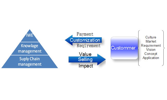
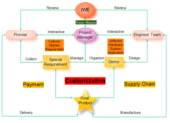
IWE-Interactive-requriment and service
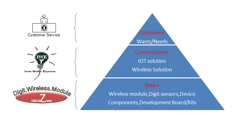
IWE-Introduction-Basic structure
Our team includes Project Manager, hardware engineers, software engineer, structure and the expert in the wireless application.We will make sure the solution will bring the value to customers.we deeply believe the power of the new organization and good management for the talent people and resource.we deeply believe the beauty of new thing we can create if we can have good organization and Management for the talent people and Manager. We attribute the success to the good management of the supply chain in the past, We believe the Success will come good management of the supply chain and also the good management and the new way of the organization to the talent workers.
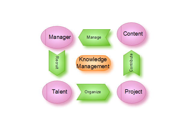
IWE-Management-knowledge management
What we are doing?
IWE-idea worth express what we are doing.
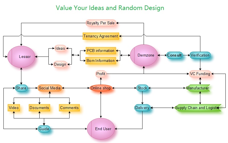
First, we will source special application, find the experts in the special area, Analysis the technic portions and then find the right people form a team.
Second, The team will build a demo to show how the system works and present the ability building a beauty product. at the same time, we have a service from IWE to help tell the story and explain the system of the application by using pictures, videos, and articles to the potential customers through the internet and social media network.
Third, the demo will be available on the online shop after it finished. The potential customers will pay for the demo and check the function have the basic idea about how it works and know the core value of this application, then a new idea brings out according to the local market and their key resource to their customer.
Fourth, After checking the demo customer will have the new idea for their application and confirm the ability of the team, then the customer has to pay a fee for customized their new product.
Fifth, IWE has a good management for the local supply chain and will source the feasible components and device from the local and international suppliers, guarantee the ability and quality when the new products run mass production.
Sixth, Using the international logistical delivery the products to the customer all over this world.
Value and impact
We take off the best skill and talent from a talent people and input that skill and talent to solutions, we help to present and explore that to customers, Customer can combine the local culture, market and requirement to the solutions to customized special products, bring the value from skill people to the end customers.We want customer can have full service for supply chain and talent people at one station.We want the talent people to have more time with their families and friends or for traveling.
Idea worth express this is a great journey join with us start the big adventure
For further information please contact us:
E-mail: sales@odlstore.com Skype: ameisina
Twitter:Dwmzone Facebook:Dwmzone
Youtube:Dwmzone
Website: http://www.odlstore.com