Author Archives: Ameisina

About Ameisina

I am living shenzhen the 4th biggest city in china. I do some business with some friends and customers oversee. I try to intruduce the biggest E-component market in the world it's HUAQIANGBEI. I will express with seriess with the life here and the merchanter How they Living for. The most importance parts is I will intruduce the thousands components , parts and device.

E931.96 Ultra-Low Power PIR Controller Integrated Circuit

E931.96 Ultra-Low Power PIR Controller

General Description

The E931.96 is an ultra-low power motion detector controller integrated circuit. The device is ideally suited for battery operated wireless motion sensors that make use of an MCU for handling communication. The MCU does not need to be active while the E931.96 does continuous motion sensing. It only activates the external controller, when motion is
detected. Motion is signaled through the push-pull output (INT). The criteria for motion detection are programmable and can be changed by the external controller.
The E931.96 interfaces directly with up to two conventional PIR sensors via a high impedance
differential input. The PIR signal is converted to a 14 bit digital value on chip.All signal processing is performed digitally.The E931.96 is available in a SOIC-8 package.

Applications

 Wireless intruder detectors
 Battery powered door chimes
 Emergency lighting
 Motion and presence detection

Features

 Programmable detection criteria and operating modes
 Digital signal processing
 On chip supply regulator for conventional PIR detectors
 Ultra Low power consumption
 Differential PIR sensor input
 Supply voltage measurement
 Temperature measurement
 Instantaneous settling after power up

Application Circuits

dwmzone-e931.96-Application-Circuits-1

Fig 1: Wireless Intruder Detector

Fig 1: Wireless Intruder Detector

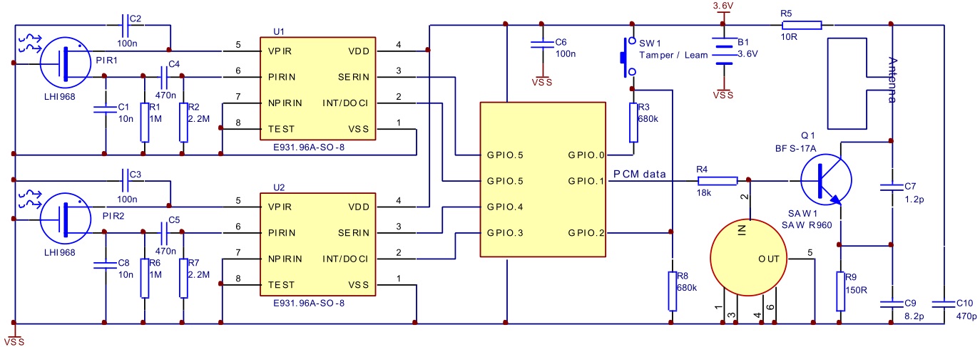
Wireless Intruder Detector with Two Controllers

Fig 2:Wireless Intruder Detector with Two Controllers

Fig 2:Wireless Intruder Detector with Two Controllers

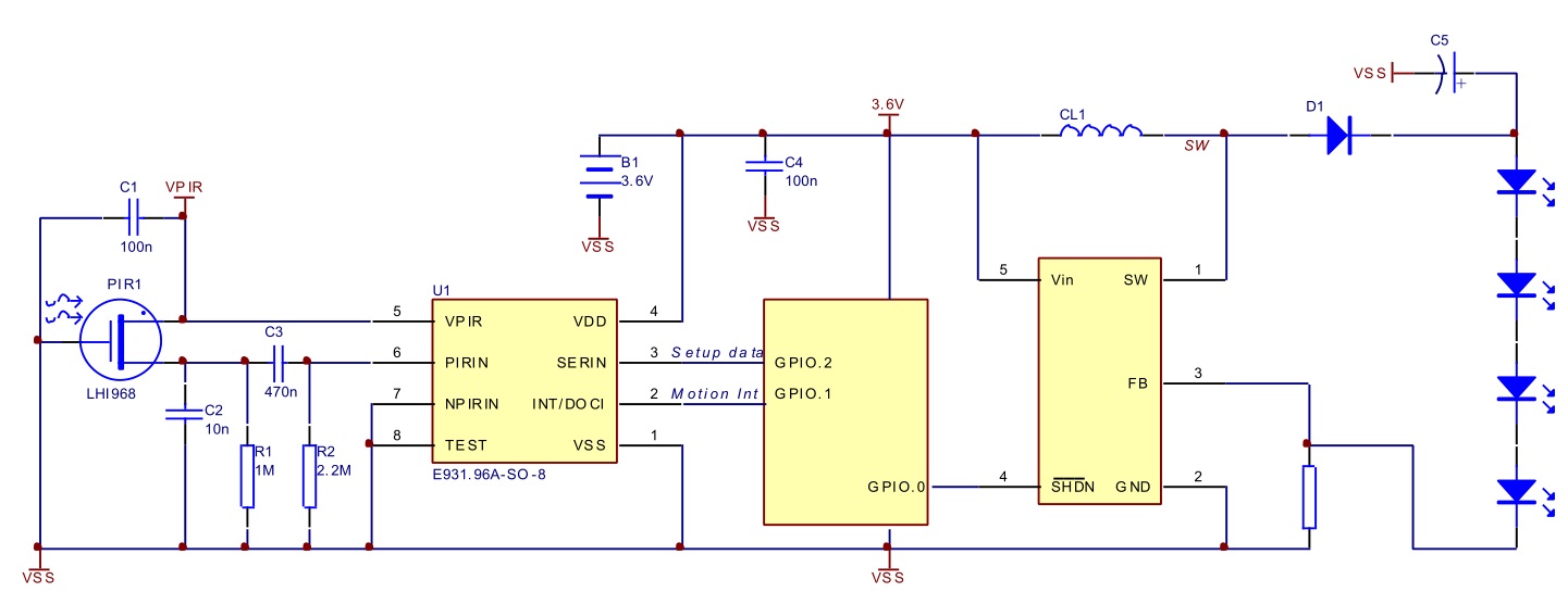
Emergency Lighting

Emergency Lighting

Fig 3: Emergency Lighting

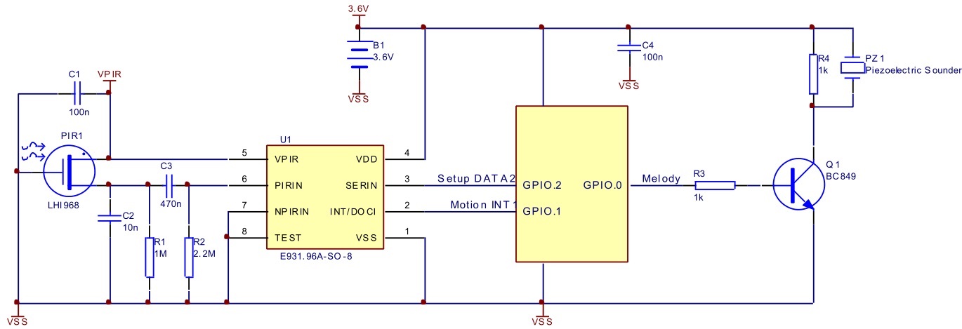
Door Chime

Door ChimeFig 4: Door Chime

Fig 4: Door Chime


Electrical Characteristics

Absolute Maximum Ratings

Absolute Maximum Ratings

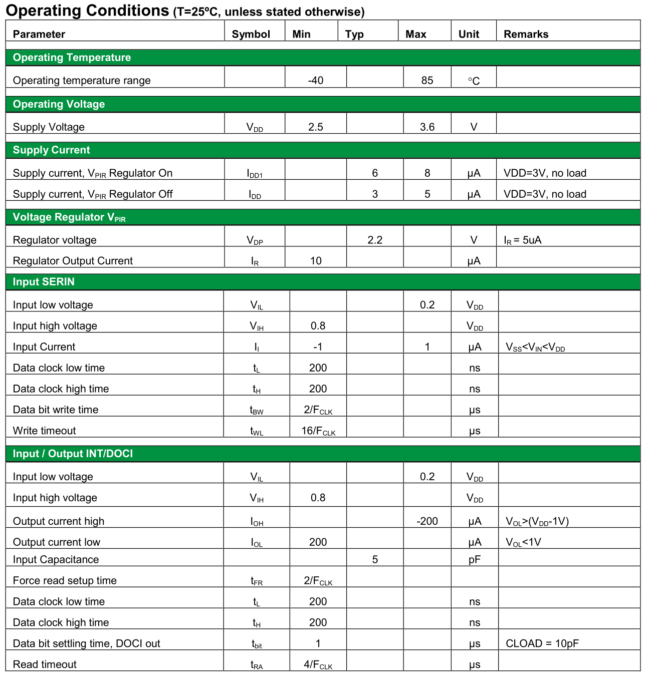
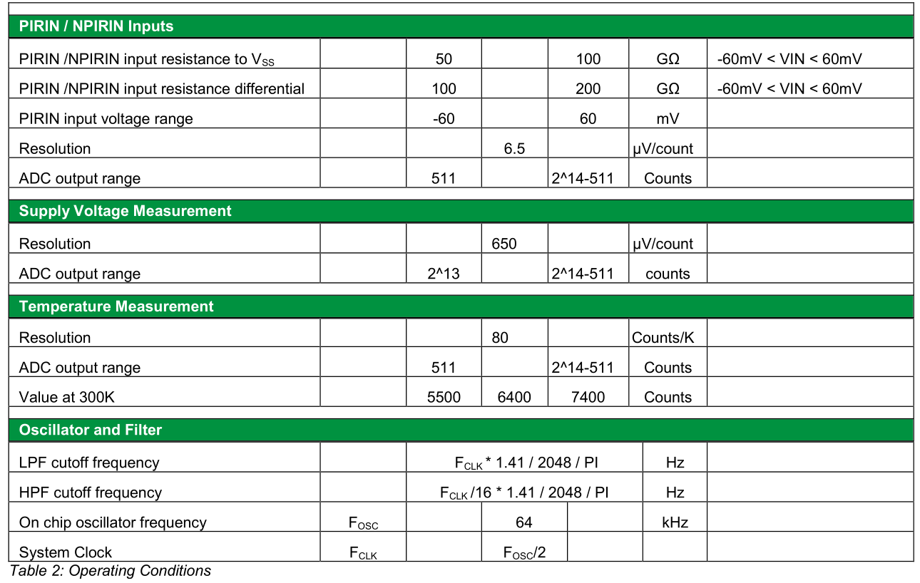
Operating Conditions

Operating Conditions

Operating Conditions

Operating Conditions

Detailed Description

Detailed Description

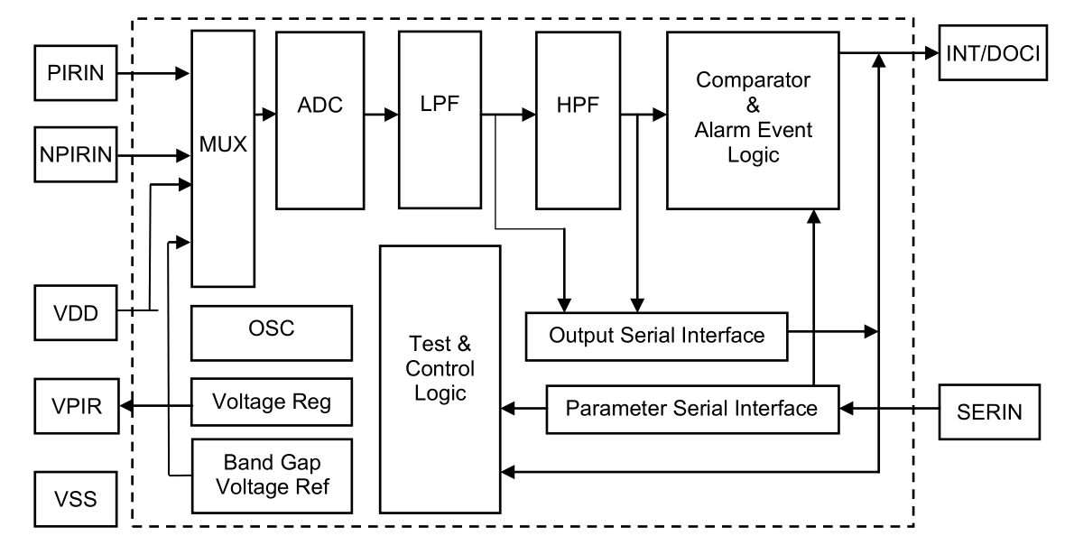
Fig 5: Block diagram of E931.96

Fig 5: Block diagram of E931.96

MUX

The multiplexer selects the source signal for the ADC. It can select between the differential PIR inputs, differential temperature sensor output and asymmetrical supply voltage divider.

Voltage Regulator

The integrated voltage regulator provides a regulated 2.2V supply for an externally connected conventional PIR detector. The regulator can be activated through the control register.

Bandgap Voltage Reference

The bandgap voltage reference provides constant reference currents and voltages to the analog circuitry on chip across the specified operating temperature range of the device.
In addition, it contains a temperature voltage generator (temperature sensor).

Oscillator

The IC contains an on chip low power oscillator. The frequency is set to 64kHz. The timing signals and cutoff frequencies of the digital filters are derived from this frequency.

Band-Pass Filter

A 2nd order low-pass filter with a cut-off frequency of 7Hz eliminates unwanted higher frequency components. This signal is then passed to a 2 nd order high pass filter with a 0.4Hz cut-off frequency. Both filter output are accessible through the serial interface.

Alarm Event Logic

The signal from the band pass filter is rectified. When the signal level exceeds the sensitivity threshold, an internal pulse is generated. Subsequent pulses are counted, whenever the signals changes sign and exceeds the threshold again. The conditions for an alarm event such as the amount of pulses as well as the time window in which the pulses occur are programmable.
If an alarm event is cleared by resetting the interrupt output (by the device or through the external MCU), any motion detection is stopped during the programmable blind time. This feature is important to prevent self-triggering in applications, where high detection sensitivity is required.

Serial Interface

The device setup is done by programming setup registers via the SERIN pin. A simple clocked data-in protocol is used.Information from the device is read out with the INT/DOCI pin. A similar clocked data-out protocol is used.

Configuration Register

The device contains a configuration register. Write access is through the serial input. Read access is performed through the interrupt output.
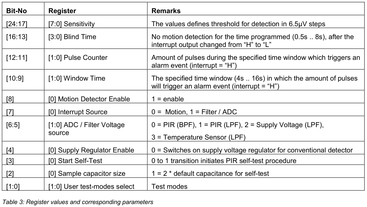
The following parameters can be adjusted through the control / configuration registers:

1. Sensitivity

The sensitivity / detection threshold is defined with the register value. The resolution of the register is 6.5µV.The threshold is [Register Value] * 6.5µV

2. Blind Time

Ignores motion after the interrupt output is switched back to 0
Range: 0.5s… 8s. The blind time is [Register Value] *0.5s

3. Programmable pulse counter

1… 4 pulses with sign change in between Amount of pulses = [Register Value] + 1

4. Window time

For noisy environments 4s… 16s window Window time = [Register Value] * 4s + 4s

5. Motion Detect Enable

0 = disable, 1 = enabled

6. Interrupt Source

The interrupt source can be selected between Motion (default) or ADC Decimation Filter. If the decimation filter is selected, interrupts are generated every 14ms. 0 = Motion, 1 = Filter
The Interrupt can be switched off by setting the mask bit to Motion and switching off the motion detector function.

7. Voltage Source

There is only one ADC integrated on chip. The following source voltages are selectable for the ADC:
PIR Signal, BFP Output = 0
PIR Signal, LPF Output = 1
Chip Supply Voltage = 2
On Chip Temperature Sensor = 3
For Motion Detector Mode, ‘0’ or ‘1’ has to be selected.

8. Supply Regulator Enable for conventional PIR Detector (2.2V)

Supply a regulated 2.2V on the V REG output.
1 = disabled, 0 = enabled

9. Start Self-Test

Initiates PIR self-test procedure that takes 2seconds to complete.
0 to 1 change = start

10. Sample Capacitor Value

For different size pyro ceramics, different sample capacitors can be selected for the pyro ceramic test

11. User test-modes

Reserved, program with 0

Serial Data Input

The configuration data is transferred into the device via the serial input. The external microcontroller has to generate a zero to one transition on the SERIN input and subsequently apply the data bit value (0/1). The ‘zero’ and ‘one’ time for the transition can be very short (1 instruction cycle of the microcontroller). The data bit value must be applied for at least 2 system clocks (t bit ) of the E931.96A. Whenever the transfer of data bits is interrupted for a period greater than 16 system clocks (t R ), the last data received is latched into the configuration register. The transmission of a 25 bit data should not be interrupted for more than 15 system clocks, as the device may latch the data already at this stage.

Serial Data clocked into device by MCU

Serial Data clocked into device by MCU

Fig 6: Serial Data clocked into device by MCU

Register values and corresponding parameters

Register values and corresponding parameters

Serial Data Output / Interrupt

The serial output serves as an Interrupt output, indicating motion and as a serial output for reading status and configuration data from the circuit.

Read Procedure

The E931.96 accepts readout with MCU defined timing. The MCU has to force DOCI to a high level for the duration of more than 2 device clock cycles (t FR ) and subsequently read out the data bits as described in the timing diagram below.Reading can be terminated at any time by forcing the DOCI line to “0” for at least 4 system clock cycles.

Timing diagram for the DOCI interface

Timing diagram for the DOCI interface

The interrupt source for the DOCI / INTR output can be selected between the ADC and the motions detect logic. If the ADC is selected, an interrupt is produced every 512 system clocks. If not, the alarm event logic will set the interrupt, whenever it detects motion AND motion detection is activated. No interrupt will be generated while the microcontroller accesses the interface.

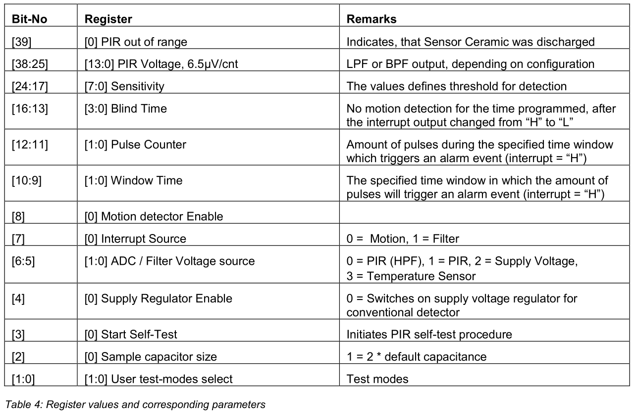
Status and Configuration Data

The PIR voltage as well as all internal data can be read through the DOCI interface. The sequence of the data is fixed due to priority. The device outputs the PIR voltage value first, followed by status and configuration information. It is not required to read all data.

Data words available on DOCI interface

Data words available on DOCI interface

Register values and corresponding parameters

Register values and corresponding parameters

PIR Voltage Measurement

a) LPF Output
The ADC Source [6:5] has to be switched to the PIR inputs and the digital LPF output needs to be selected (=1).
V PIR = (ADC_out – ADC_offset) * 6.5µV.
b) HPF Output
The ADC Source [6:5] has to be switched to PIR input and the digital HPF output needs to be selected (=0).
V PIR = ADC_out * 6.5µV.

Supply Voltage Measurement

The ADC Source [6:5] has to be switched to Chip Supply (=2).
V DD = (ADC_out – ADC_offset) * 650µV.

Temperature Measurement

The ADC Source [6:5] has to be switched to the temperature sensor (=3).
Temperature = Tcal + (ADC_out – ADC_offset(Tcal)) / 80 * counts/K
ADC_offset = ADC value @ VIN = 0, typical value = 2^13
ADC_offset(Tcal) = ADC value at defined ambient temperature, typical value = 6400@300K

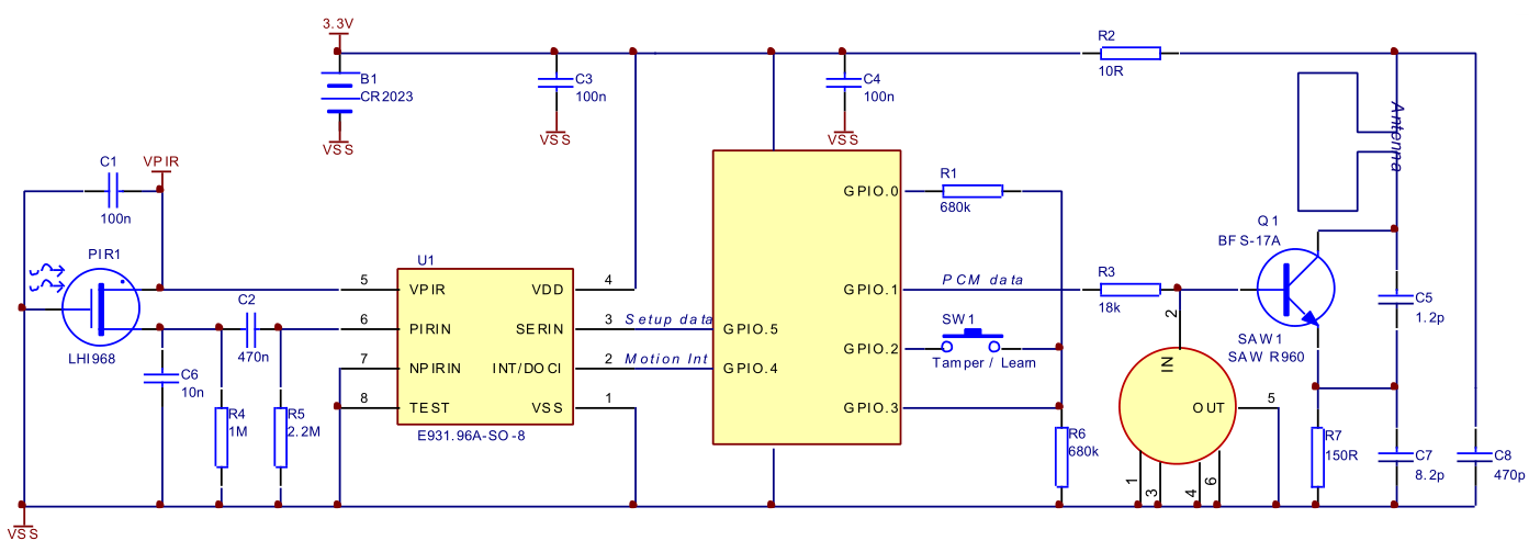
SOIC8 Pin Out

SOIC8 Pin Out

SOIC8 Pin Out

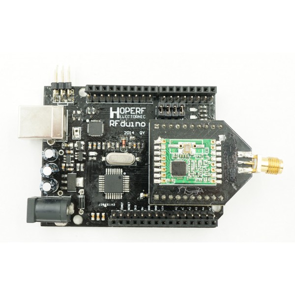
RFduino Board & LoRa module as DK board User guide

     RFduino Board original design for all of the Wireless modules can share with same Library and can run a Wireless communication code with the RFduino Board.This User guide will show you how to use the RFduino Board to delevelop the RFM92W,RFM95W,RFM96W,RFM98W  LoRa module etcs.

    RFduino Board which also name HopeDuino But we used to call it as RFduino board.If there are any questions please contact us sales@odlstore.com. We will give more details about the name.

If you are  the firt time use the   RFduino Board please visit the  RFduino Board User Manule.

  1. Prepare Hardware and software:

2. Operation

 1.) Set two RFM9X LoRa module to The RFduino Board .

rfduino-board

2.) Connect the RFduino Board to the PC by USB cable.

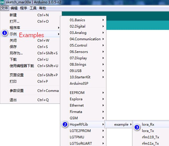
   3.) Opens the Arduino IDE interface, click on the [file] – > [Examples] -> [HopeRFLib] ->[lora_Tx], below operation;

   4.) Opens the Arduino IDE interface, click on the [file] – > [example] -> [HopeRFLib] -> [lora_Rx], the following figure.

Dwmzone-LoRa-module-RFduino-board

5.) Compile and download the Software.

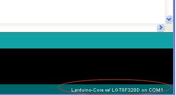
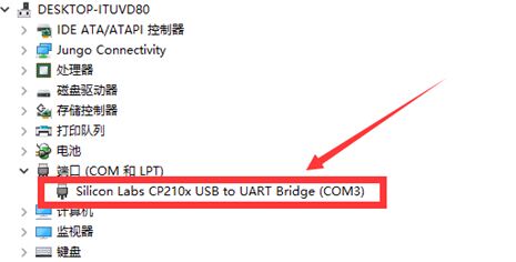
Since there are two USB cable connect to one PC and one Aduino ID there are onething need to be carefull that’s the Serial port,each of time you compile and download the LoRa_Tx and LoRa_Rx You have to choice the correct Serial Port.You can see the serial port on the right down corner which shows as below:

Dwmzone-LoRa-module-RFduino-board-serial-poart

 6.) Serial Port Monitor the TX and RX communication.

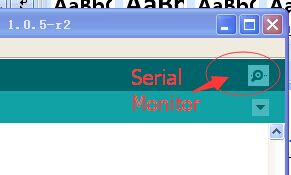
After Compile and download the Software the TX will start the wireless transmission periodically and you can set the Rx serial port and check the received data package by click the “Serial Mornitor”.

Dwmzone-LoRa-module-RFduino-board-serial-poart-monitor

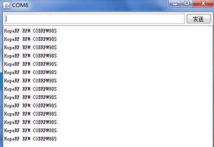
It will open a new windows and display the data received.shows as below:

Dwmzone-LoRa-module-RFduino-board-serial-poart-data

Note: You can check the UART Library  which content the function for UART communiction here is the Route: HoepRF-HSP->libraries->HopeRFLib -> HopeDuino_UART.

3.Paremeter Definition and Description.

“LoRa. H” and “LoRa. CPP” library file repository paths in the Arduino IDE folder/libraries/HopeRFLib;

  •  FreqStruct
    Type:  Union type
    Description: for RFM9X frequency register definition
    Content: the Freq, long, 4 bytes, frequency values;
            FreqL, bytes, in view of the Freq split the low frequency values of 8 [0:7];
            FreqM, bytes, in view of the Freq split the frequency values of 8 [8:15];
            FreqH, bytes, in view of the high Freq split frequency values of 8 [16:23];
            FreqX, byte, redundancy, rounding 4 bytes, No meaning.
  • Modulation Type
    Type: enum-type
    Description: select Modulation and demodulation system
    Content: OOK, FSK, GFSK, LORA
    OOK: ON-Off – the Key ;
        FSK:  Frequency – Shift – Key:
       GFSK: FSK modulation with gaussian filtering;
        LoRa :Semtech characteristic spread spectrum modulation technique.
  • moduleType
    Type: enum-type
    Description: select the target module models
    Content: LoRa module EVB/DK Kits(RFM92W,RFM95W,RFM96W,RFM98W).
  • sfType
    Type: enum-type
    Description: define LoRa mode, spreading factor (SF – spreading factor)
    Content:  SF6, SF7 SF8 SF9, SF10, SF11, SF12.
  • Modulation
    Type: modulationType type
    Description: define modulation demodulation system, OOK, FSK, GFSK,LoRa by selecting one of the them.
  • COB
    Type: moduleType type
    Description: definition module model, COB said Chip – On – Borad, can be choice from LoRa module EVB/DK Kits(RFM92W,RFM95W,RFM96W,RFM98W).
  • Frequency
    Type: type lword (unsigned long)
    Description: the target operating Frequency, the unit KHz, such as: Frequency = 433920, on behalf of 433.92 MHz.
  • SymbolTime
    Type: type lword (unsigned long)
    Description: the target rate, the unit ns, such as: SymbolTime = 416000, representing 416 us each symbol, It means the rate is 2.4 kbps.
  • Devation
    Type: type lword (unsigned long)
    Description: the target work frequency deviation, in view of the FSK and GFSK launch needs to be defined, unit KHz, for example: Devation = 45, It means the Frequency Deviation is 45 KHz.
  •  BandWidth
    Type: type of word (unsigned int)
    Description: the target work receive BandWidth, for receiving need to define the unit KHz, for example: BandWidth = 100, on behalf of the receiving BandWidth is 100 KHz.
  • OutputPower
    Type: unsigned char
    Description: the target output power, in view of the need to define the launch, range 2-20, unit dBm, for example, is set to 10 means the Output Power is 10 dBm.
  • PreambleLength
    Type: type of word (unsigned int)
    Function: Preamble of packet length setting, need to be configured for launch, byte units.
  • CrcDisable
    Types: bool type
    Description: choose whether or not to bring in a packet function CRC, set true representative prohibit CRC function;Set up false open CRC function.
  • FixedPktLength
    Types: bool type
    Description: define packet is fixed packet length, or longer packets, set true representative fixed packet length;Set the false on behalf of the variable-length packet format.
  • SyncLength
    Types: Byte type
    Description: wireless packet format, the synchronization word length, set the range is 1 ~ 8 bytes;Cannot be set to zero bytes.
  • SyncWord [8]
    Type: an array of bytes
    Description: set the packet format, the synchronization word, the content of the need and SyncLength set in accordance with (length).
  • PayloadLength
    Types: Byte type
    Description: in fixed packet length model, defining fixed packet length.
  • SFSel
    Type: sfType type
    Description: set LoRa mode of spread spectrum factor, can choose SF6, SF7, SF8, SF9, SF10, SF11, SF12 one of them.
  • BWSel
    Type: bwType type
    Description: set LoRa mode emission bandwidth parameters, can choose BW62K, BW125K, BW250K, BW500K one of them.
  • CRSel
    Type: crType type
    Description: set the CodeRate LoRa mode, can choose CR4_5, CR4_6, CR4_7, CR4_8 one of them.
  • PayloadLength
    Type: Byte type:
    Description: in fixed packet length model, defining fixed packet length.
  •  SFSel
    Type: sfType type
    Description: set LoRa mode of spread spectrum factor, can choose SF6, SF7, SF8, SF9, SF10, SF11, SF12 one of them.
  • BWSel
    Type: bwType type
    Description: set LoRa mode emission bandwidth parameters, can choose BW62K, BW125K, BW250K, BW500K one of them.
  • CRSel
    Type: crType type
    Description: set the CodeRate LoRa mode, can choose CR4_5, CR4_6, CR4_7, CR4_8 one of them.

4.Function Definition and Description.

  • vInitialize
    Type:Function
    Parameter: none
    Return value: none
    Description: initialization module (chip), suitable for RFM66 module, the program started calling;Before the call, it is necessary to the foregoing associated variable is set to complete.Initialization function after the configuration (including call vConfig function), that module (chip) for Standby state, namely, not hair, not closed, not sleep.
  • vConfig
    Type: Function
    Parameter: none
    Return value: none
    Description: configuration parameters to the module (chip), applicable to the program need to reconfigure the parameters in the process of work.Also need to complete the associated variable is set before invoking it.If the associated variables set up complete, the follow-up is unchanged, only want to reconfigure a parameters, can be called directly;If need in the process of work, the work of switching frequency, etc., need to modify the relevant parameters, and then in the call.After the call, need to use working mode switching function, so that the chips accurately to the specific work mode, the mode switching function are: vGoRx, vGoStandby, vGoSleep etc.
  • vGoRx
    Type:Function
    Parameter: none
    Return value: none
    Description: configuration module (chip) into the receive mode.
  • vGoStandby
    Type: Function
    Parameter: none
    Return value: none
    Description: configuration module (chip) to enter standby mode.
  • vGoSleep
    Type: Function
    Parameter: none
    Return value: none
    Description: configuration module (chip) into sleep mode.
  • bSendMessage
    Type: function
    Parameter: MSG [], unsigned char pointer type, with emission data array called entrance (pointer);Length, unsigned char types, to launch the data length, the unit is byte;
    Return Value: returns a bool type, true indicates the successful launch;False indicates failure to launch, such as: push a timeout, and so on and so forth;
    Description: the data are sent to launch, just send a (a frame);Sent after the completion of automatic return to Standby mode (Standby mode).
  • bGetMessage
    Type: Function
    Parameter: MSG [], unsigned char pointer type, calls for receiving data array entry (pointer);
    Return Value: return value is the length of the receiving data, if it returns 0 means no received data;
    Description: query whether receives the data, the query object is chip output IO state, if not received data, returns 0;If the received data, returns the length of the received data, after the charge, module (chip) is still in a state of receiving.

5.PIN definition

RFDuino Board MCU (Lgt8f328) RFM9x modules(Or Chipset)
13 PB5 SCK
12 PB4 MISO
11 PB3 MOSI
10 PB2 nCS
9 PB1 POR
8 PB0 DIO0
7 PD7 DIO1(Jumper
6 PD6 DIO2(Jumper)
5 PD5 DIO3(Jumper)
4 PD4 DIO4(Jumper)

RFduino Board User Manule

RFduino Board User Manule

RFduino Board which is compatible with Arduino UNO R3 and Arduino IDE. We recommand you use the Source Arduino 1.0.5 as IDE.

RFduino Board which also name HopeDuino But we used to call it as RFduino board.If there are any questions please contact us sales@odlstore.com. We will give more details about the name.

1.Prepare Hardware and software:

2.Installation

   1.) Arduino IDE installation
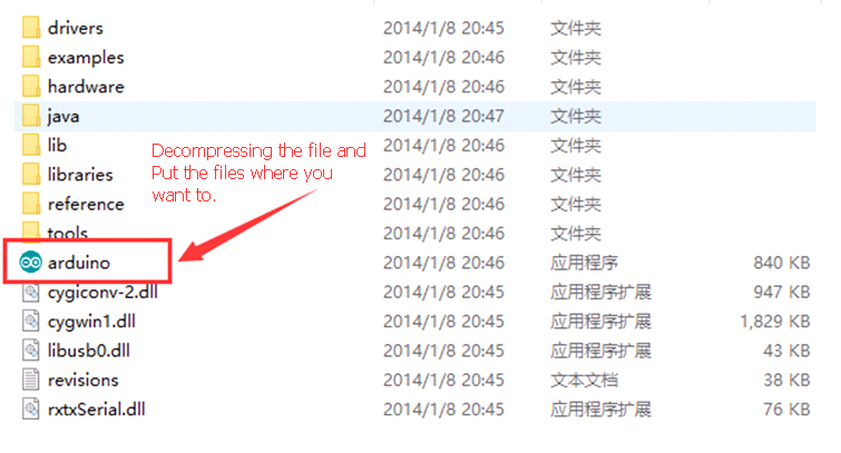
   Download the Arduino 1.0.5 package extract directly to need to put the path, this version is free of installation.As shown in the figure below:

dwmzone-Arduino-IDE installation

  2.) CP2102 chip driver installation

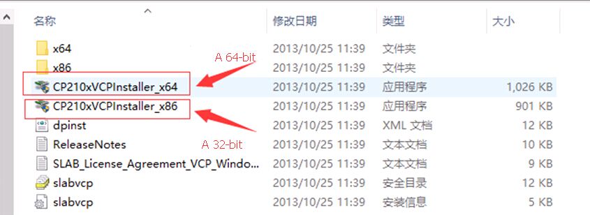
Download “CP210x_VCP_Windows” decompression, in computer system, according to you choose a 64 – bit or 32-bit drivers, double-click the install.As shown in the figure below:

dwnzone-CP2102-chip -driver-installation

3.) Installation HoepRF-HSP hardware and softare service package(Click and download directly).

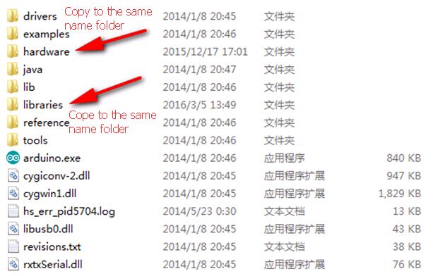
Download the “HoepRF-HSP“hardware and softare service package decompression,you can find two folders “hardware” and “libraries”, Copy the Files under those two folders to the Arduino 1.0.5 “hardware” and “libraries” folders which has the same name.As shown in the figure below:

dwmzone-Installation-HoepRF-HSP

Copy the content of the “hardware” in HoepRF-HSP to the file Arduino 1.0.5 “hardware”.

dwmzone-Installation-HoepRF-HSP-Hardware

Copy the content of the “libraries” in HoepRF-HSP to the file Arduino 1.0.5 “libraries”.

dwmzone-Installation-HoepRF-HSP-Libarry

4.) Connect the RFduino board to PC through the serial port.

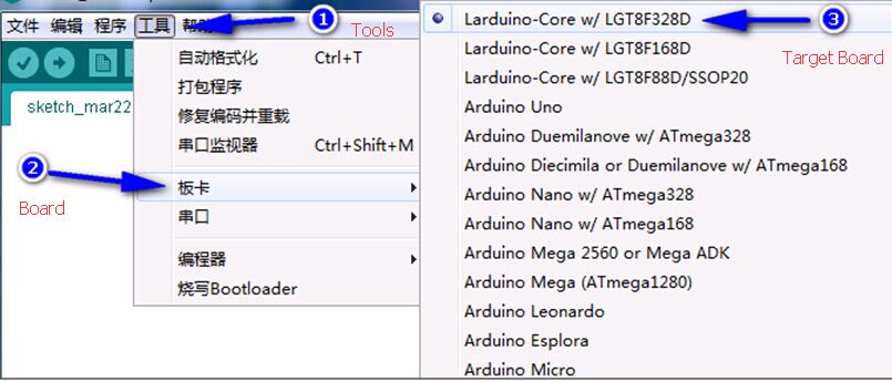
Double-click the arduino. Exe “to open the arduino IDE interface, the interface of select [ToolS] -> [ Board] -> [Larduino core w/LGT8f328d ], as shown in the figure below:

dwmzone-Connect-the-RFduino-board-PC-port
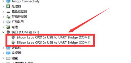
After connect two board you will see as below:
dwmzone-Connect-the-RFduino-2-board-PC-port
3. Arduino IDE Setting
  Double-click the arduino. Exe “to open the arduino IDE interface, the interface of select [Tools] – >[Board] – >[Larduino core w/LGT8f328d 】, as shown in the figure below:
dwmzone-Arduino-IDE-Setting
4. Test LED Blink
After we finished the IDE setting the we can run a test to make sure thoes board works:
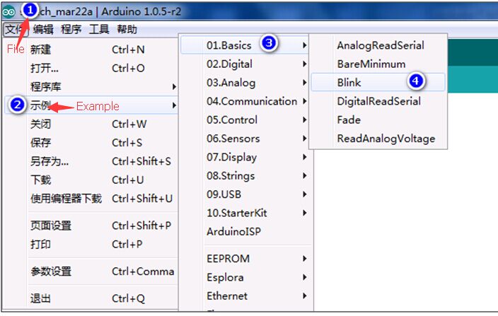
Select [file] – > [example] ->[01. Basics] -> “Blink”, as shown in the figure below:
dwmzone-Arduino-IDE-Setting-LED-Blink
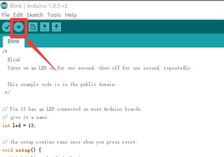
At this time will re-open the Blink routine file, as shown in the figure below, click on “compile and download”.
dwmzone-Arduino-IDE-LED-Blink-Compile
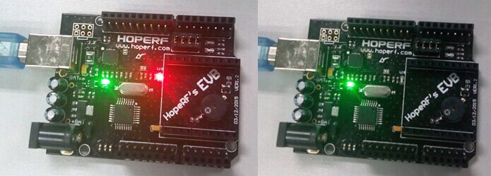
After compiling finished and download software to RFduino board, after the download is complete, the red LED (L13) will according to the interval of 1 second, Means download success,  Shows as the following figure:
dwmzone-Arduino-IDE-Setting-LED-Blinking
5.Ending
You can continue and Enjoy all of the series wireles modules Function which various corresponding validation HopeRF routines for you need to test.

Balanbot Assembly Instruction

1,reveal the acrylic’s protection paper.
1
2,assembly 3 acrylic board with accessories like this:
2
3
4
5
6
7
8
9
3,assembly motor and battery acrylic board together with screw m3x8.
Put the motor’s wires out through holes on the board and tie them up.

10
11
4,connect DC header to holder’s wires.
put three 18650 batteries into the holder and fasten with nylon ribbon.

12
5,assembly the controller acrylic board last with screw m3x8 too.
Put the wires out through hole on the board

13
6,connect motor wires and balance shield.
Left motor connect to M1.(longer wires stand for motor1)
Right motor connect to M2.(shorter wires stand for motor2)

14
15
7,assembly ties with screw m4x6

8,download codes
16

9,finish.

Note:
If you want to control balanbot by bluetooth,connect bluetooth like this:
17

Travel Tip: Where Your Favorite Travel Gadgets are Banned

Who doesn’t love travel gadgets? Well, as it turns out, not everyone is a fan. In some cases, your brand-new toy might actually be banned.

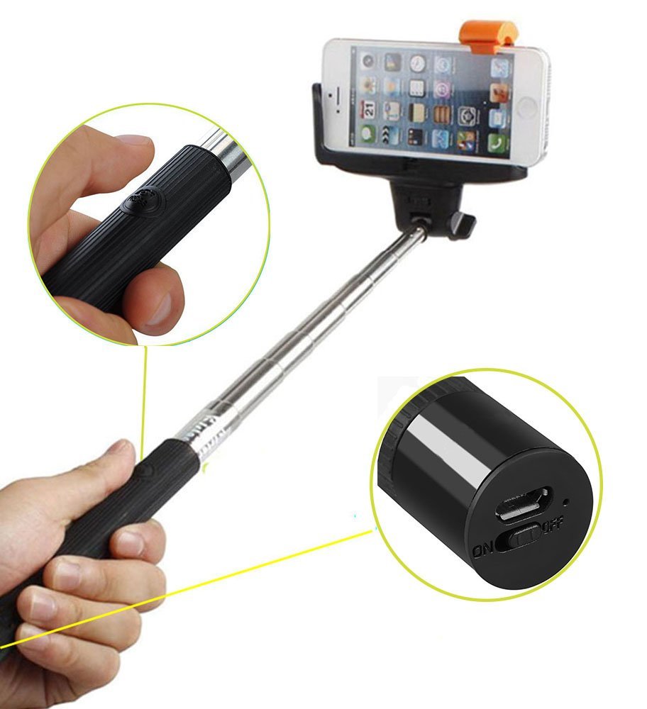
The Museum of Modern Art in New York, the Getty Center in Los Angeles, and several Smithsonian museums in Washington, D.C. have banned people from bringing selfie sticks on the grounds. Selfie sticks are the portable sticks that attach to your smartphones.

Officials say they’re most worried about the sticks damaging the exhibits, and they pose a safety issue for other patrons.

Can’t wait to break out your new drone to take aerial photographs? Not so fast. National parks are considered “no-drone zones,” based on concerns over noise and safety.

Plus, you might remember a few months ago, when people started getting into brawls in the air. No, it had nothing to do with drink service or noisy passengers.

The fights were due to something called a Knee Defender, which prevents seats from reclining.

Well, guess what? They’re banned by most major airlines.

So unfortunately, the gadgets you bought specifically for travel are going to have to stay home for a while.


dwmzone selfie stick